My Projects
- Sharp phase field models for microstructure evolution
- Dislocation assisted phase separation and coarsening
- Surface diffusion enhanced disintegration of nanowires
- Multiscale model for equilibrium stacking fault width calculation of alloys
- Phase field crystal models for defect microstructures
- Electron-phonon interaction corrections in total energy of group IV semiconductors
- Slip transfer at a boundary in discrete dislocation dynamics simulations
Last updated: July 24, 2026
Sharp phase field models for microstructure evolution
I have been chasing this development in the phase field literature since the later part of my PhD. The method is a very promising approach to eliminate grid pinning and deal well with interfaces that are resolved with fewer grid points. The basic method involves the determination of a free energy functional in such a way that the interfacial energy remains constant during every step in the translation of the interface from one grid point to the next. The development of the free energy functional for the 1-D case and subsequent generalizations into the 2-D and 3-D cases are made elegantly in the original article by Professor Finel and co-workers (although, it took me a while to figure out all the steps in between).
In a standard discrete phase-field model, the energy of an interface can depend on where the interface falls relative to the mesh. That is a numerical artifact: the physics should not change just because the interface is shifted by a fraction of a grid spacing. This work seeks a function $g(\phi)$ and a discretization such that if one profile $\phi_n = f(nd)$ is a stationary solution, then the shifted profile $\phi_n = f(nd - x_0)$ is also stationary for any shift $x_0$. A practical consequence is that the interfacial energy becomes much less sensitive to grid placement, which is especially useful when studying moving or curved interfaces.
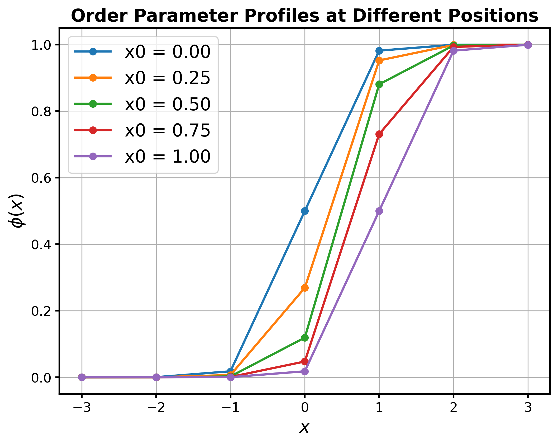
The model starts from a discrete free-energy functional of the form
\[F = d \sum_n \left[g(\phi_n) + \frac{\lambda}{2 d^2} \lVert \nabla \phi_n \rVert^2 \right].\]Here, $\phi$ is the phase field, $d$ is the grid spacing, $\lambda$ controls the interface cost, and $g(\phi)$ is a local energy density chosen to work well with the discrete gradient term. The evolution follows an Allen-Cahn-type equation,
\[\frac{\partial \phi}{\partial t} = -L \frac{\delta F}{\delta \phi},\]with
\[\frac{\delta F}{\delta \phi} = g'(\phi) - \lambda \Delta f(\phi).\]In the implementation, the interface orientation enters through a smooth factor based on a hyperbolic tangent profile, which helps enforce the desired invariance properties.
The function $g(\phi)$ obtained by the translational invariance of the interfacial energy is:
\[g(\phi) = \frac{\lambda}{4} \sum_{i=1}^{2} \gamma_i \frac{\nu_i}{d_i^2} \sum_{s=1}^{N_s} \left\{ \frac{1 - \alpha(\vec r_i(s))^2}{\alpha(\vec r_i(s))^2} \left( \frac{16 \phi (1-\phi)(1-2\phi)}{1 - \alpha(\vec r_i(s))^2 (2\phi - 1)^2} \right) \right\}\]where, $\alpha(\vec r_i(s)) = \tanh\left(\frac{\vec r_i(s)\cdot \vec u}{w}\right)$, $\gamma_i$ is a coefficient of the discrete laplacian operator and $\nu_i$ is the a parameter that deals with the multiplicity of each shells.
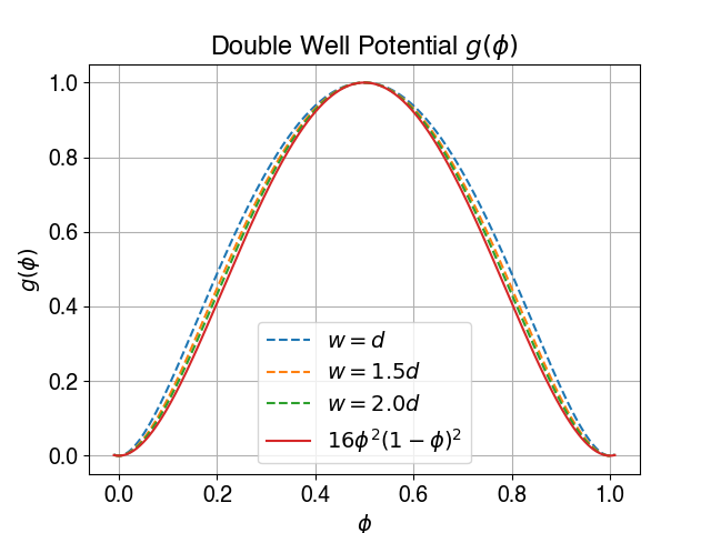
The interfacial energy in 1-D is numerically calculated as $0.44263553 \frac{\lambda}{d}$ irrespective of fractional translations of the interface.
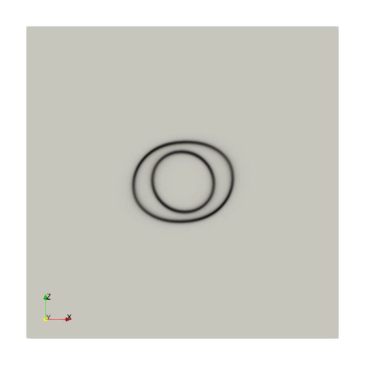
Here is a test simulation that we have done using the sharp phase field method. We are currently in-process of extending the model to incorporate elasticity.
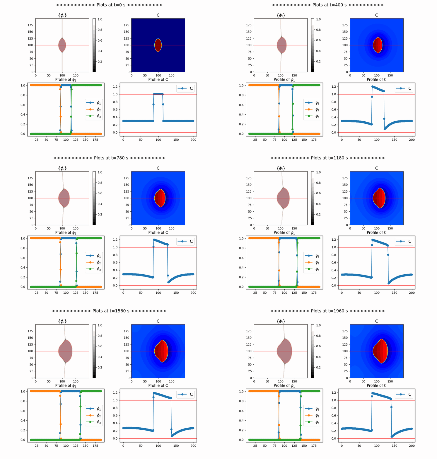
Watch this space for updates!
Dislocation assisted phase separation and coarsening
This project formed the two core chapters of my PhD thesis, on phase separation and coarsening respectively, augmented by the prescence of dislocations.
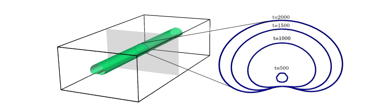
First, using a phase field dislocation dynamics model, we looked at the evolution of phases around edge dislocations in an elastically homogeneous and isotropic system that had a spinodal in its phase diagram. The presence of straight dislocation in such a system with a homogeneous initial composition (outside the spinodal limit) resulted in a segregation-driven precipitation at the dislocation. For a striaght dislocation, the precipitate would look like a cylinder with a ‘cardioid’ cross-section.
However, we are missing an important piece of physics in the above result, namely, the faster diffusivity of solutes along a dislocation, known in literature as “pipe diffusion”. By assuming the atomic mobility as a function of the dislocation field, we incorporated the faster pipe diffusivity in our model using a formulation proposed by Zhu et al..
And voila, instead of a long precipitate along the dislocation, we see blobs formed due to the growth of a composition instability. In other words, a localised spinodal at the dislocation line, in a system with an initial composition outside the spinodal limits.
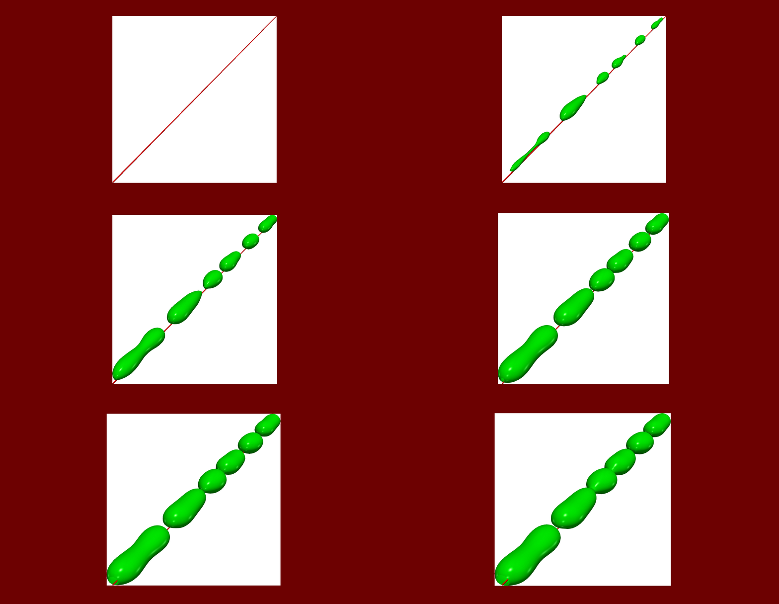
Essentially, the competition between the growth of the spinodal instability along the dislocation and the segregation from the bulk decides the phase transformation mechanism. In the first case, without pipe diffusion, the segregation dominates and spinodal fluctuations are killed. However, with pipe diffusivity, the spinodal fluctuations grow at competing rates and dominate the phase separation. This is analogous to the classic analysis by Nichols and Mullins which considers the competition between surface and volume diffusion in determining the shape evolution of cylindrical rods.
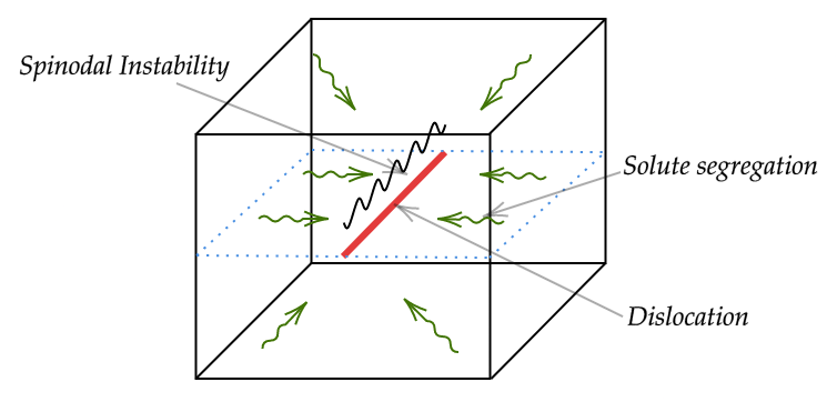
We have also mapped out the parameter space at which spinodal may be expected in systems with miscibility gap. Further, prediction of compositions at which localised spinodal might occur has been made for real-world alloys.
Please check out our publication in Acta Materialia, provided in the Publications page for more details!
The second project was to look at spherical, coherent precipitates connected by dislocations, in elastically homogeneous and heterogeneous systems, as shown here. This scenario is pretty common in several systems, where the precipitates remain coherent for longer durations while coarsening.
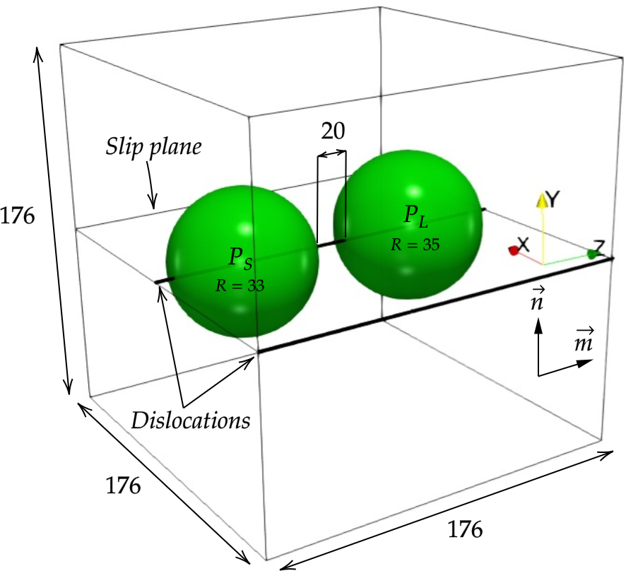
The radii of the two precipitates connected by the dislocationsa are kept at almost similar values, so as to ensure that the larger precipitate grows at the expense of the smaller precipitate. The far-field composition in the matrix phase is taken to be equal to the equilibrium concentration (calculated by modfied Gibbs-Thomson equation) for the smaller precipitate.
We then systematically study the coarsening of precipitates as a function of different parameters such as the misfit strain, elastic moduli mismatch, faster pipe diffusivity and character of the connecting dislocation. The morphology of the precipitates are altered by elastic interaction for the edge connecting dislocation case, leading to slower coarsening kinetics in the edge dislocation case.
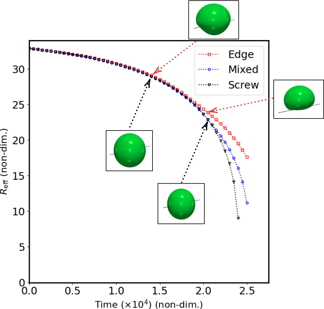
In the elastically homogeneous case, we found that only the edge dislocations elastically interacted with the precipitate, whose misfit was considered to be purely dilatational. However, in the elastically inhomogeneous case, we observe the interaction between the deviatoric components of the elastic fields as well. In addition, we calculated the average solute flux between the two precipitates and show that the apparent diffusivity of the system due to the connecting dislocations is the same as the theoretical prediction. Further, the equilibrium compositions at the precipitate-matrix interface are calculated at different points on the precipitate using the modified Gibbs-Thomson equation and compared with the compositions from the simulations.
Please check out our publication in Philosophical Magazine, provided in the Publications page for more details!
Surface diffusion enhanced disintegration of nanowires
Metallic nanowires are useful in a wide range of applications, such as, but not limited to, solar cells, flexible and stretchable electronic circuits. Hence, their stability is an important consideration, especially at high temperatures. In this study, we considered intersecting nanowires using a simple Cahn-Hilliard model, in which diffusion is assumed to predominantly occur at the surface of the wires. Due to surface diffusion, the nanowire junction undergoes a curvature driven material flow, snapping the wires at the junctions. After the nanowires break-up at the junction, the remaining parts of the wires also undergo disintegration due to Rayleigh instability.
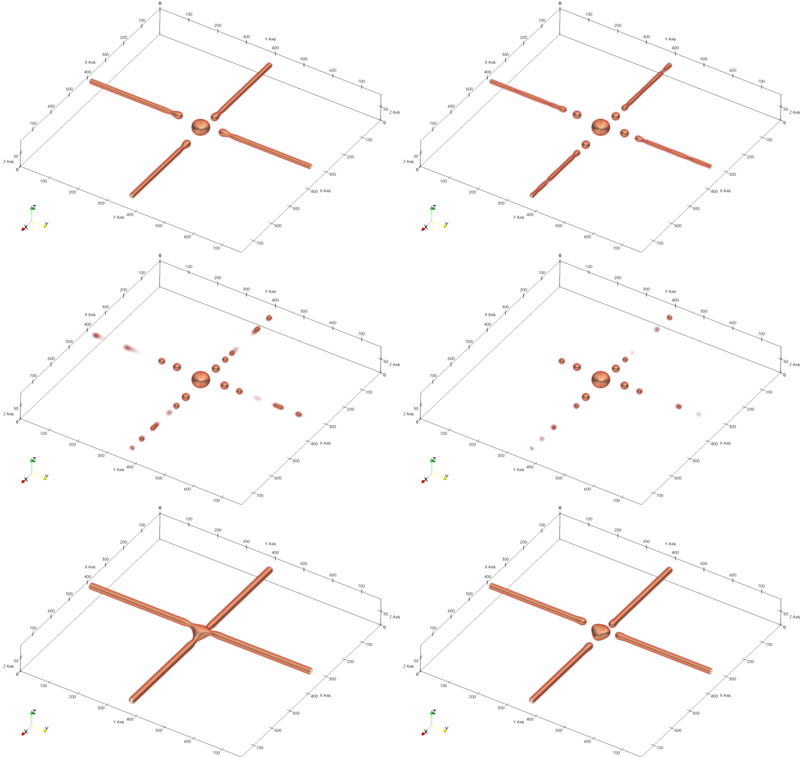
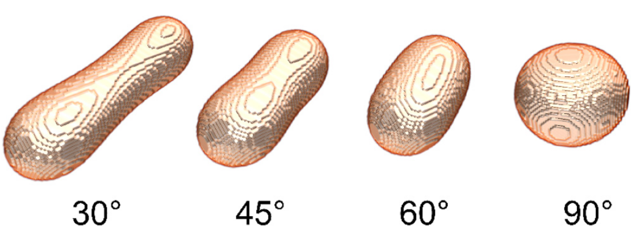
The shape of the nanodot formed at the point of intersection depends upon the angle of intersection of the nanowires. The nanodots are also symmetrically aligned along the direction which bisects this angle.
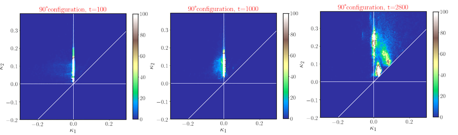
Further, the break-up of nanowires were rationalised in terms of their principal curvatures, using interfacial shape distribution (ISD) maps. The ISD maps show the evolution of the wires, from the initial cylindrical geometry, to the formation of the spherical nanodots as the wires break.
For more details, here is a link to our paper!
Multiscale model for equilibrium stacking fault width calculation of alloys
One of the most important attractions of modelling dislocations with phase field dislocation dynamics (PFDD) models is the ease of incorporating partial dislocations. This is possible by the incorporation of generalised stacking fault energy surfaces (or \(\gamma\) surfaces), obtained from atomistic simulations, as a term in the total free energy functional. It is possible to calculate the generalised stacking fault energy of a metal, using density functional theory (DFT) or molecular dynamics (MD) simulations, by sliding one layer of atoms of the metal or alloy above another over different distances and calculating the difference in energy. The resulting energy landscape consists of several peaks and valleys corresponding to the crystal structure of the system, as shown for the case of pure Cu in the following figure.
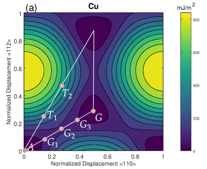
Incorporating the GSFE surface into the free energy functional after the approach by Shen and Wang (2003), it is possible to get a perfect dislocation to dissociate into a leading and a trailing partial dislocation.
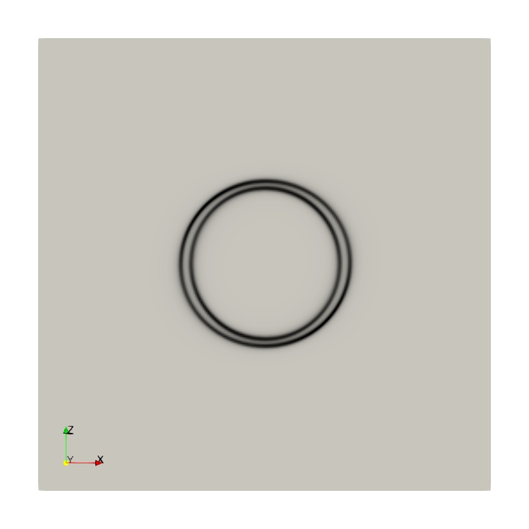
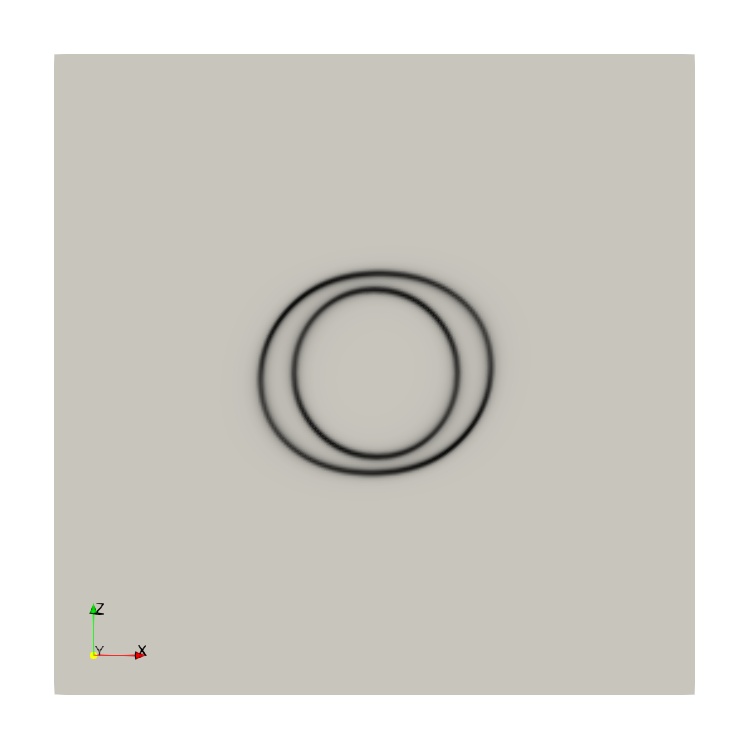
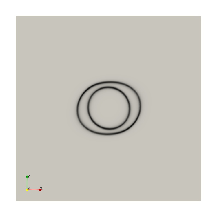
The dislocations are located by taking the derivative of the cumulative displacement that is a combination of all three Burgers vectors in the slip plane.
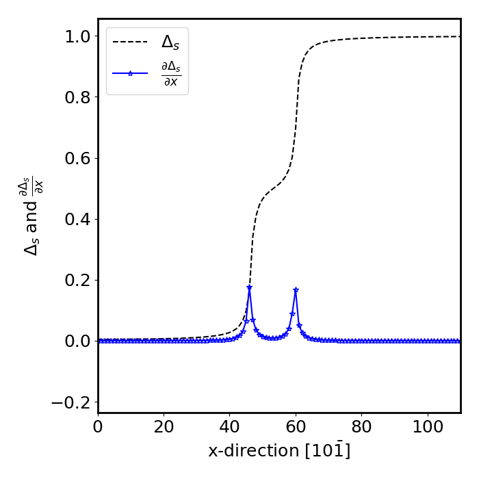
It is also possible to measure the equilibrium stacking fault of the system using this method. We are currently preparing a manuscript studying the variation in the equilibrium stacking fault width in Cu-Al system at different Al concentrations.
Phase field crystal models for defect microstructures
In September 2021, I narrowly missed a week-long intensive course on phase field crystal modelling by Professor Kuo-An Wu. But, as fate would have it, I had to eventually meet this variant again, at the group of Professor Conrard Feugmo at University of Waterloo. The idea was to generate a firm foundation for phase field crystal models in the group and work towards extending the models for a multicomponent system. The crux of the problem was in correctly incorporating the interactions between different types of atoms using the correct pair correlation functions.
We could not use the traditional approach in literature where an average density and concentration fields were used to correctly represent the microstructure. This would not be able to capture the local variations due to the long rangedness of the concentration fields. Instead, we had to use individual density fields that interacted with each other by virtue of pair-correlation functions.
Eventually, we realized that for applications that we were interested in, we had to employ three-point correlation functions, which, for the systems we were interested in, wasbeyond the reach in terms of computational resources. However, I gained quite a bit of expertise and developed several repositories of parallelized (CUDA and MPI C) solvers for structural phase field crystal method. I also developed significant experience in SymPy, Mathematica and Maple to generate the phase diagrams in the different cases.
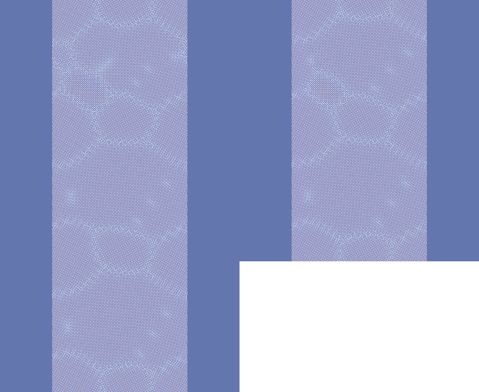
Here is an example simulation of grain growth, resolved to atomic level, by a two-component structural PFC simulation. The gif shows superimposed density fields, in black and red. This is a 2D simulation and the parameters stabilize an interpenetrating square lattice.
Electron-phonon interaction corrections in total energy of group IV semiconductors
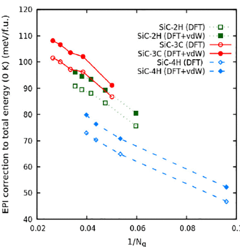
I started working on this project during the initial years of my PhD, while I was still trying to figure out what my thesis should be on. The core idea and the theoretical basis of this project belongs to Professor T R S Prasanna at MEMS, IITB. Basically, in DFT studies, the stability order of polymorphs is calculated by comparing their total energies, correcting for van der Waals (vdW) and zero-point vibrational energy (ZPVE) contributions. However, the electron-phonon interaction is also important in these calculations and can alter the energy difference between the different polytypes of carbon, silicon and silicon carbide. The incorporation of EPI corrections to the total energy was carried out by building on Allen’s formalism for quasiparticle interactions and Allen-Heine theory for electron-phonon interaction contributions at the zero point. It is observed that the EPI contribution is more sensitive to the crystal structure than the other two corrections and is an essential component of the total energy of the system. Although I do not want to claim density functional theory to be an area of my expertise, the experience with this project has made me confident enough to engage in collaboration with DFT experts.
Slip transfer at a boundary in discrete dislocation dynamics simulations
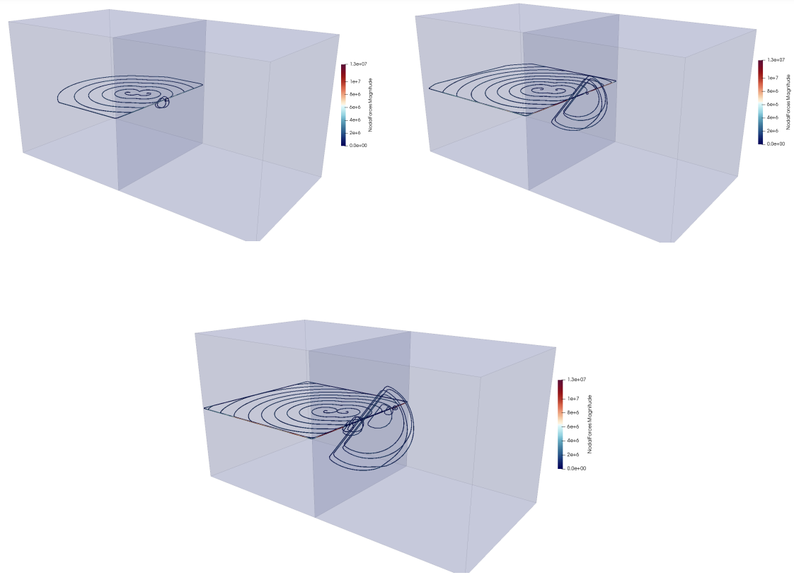
This project was part of my six month exchange program to Universit'e Grenoble Alpes. The idea was to incorporate a slip transfer module in the newly developed discrete dislocation dynamics package named NUMODIS and use it to study strain hardening in polycrystalline systems. The expectation was that a parallel version of NUMODIS would be available, from a different project, by the time our project would begin. However, the parallelization project did not go as planned and there was a severe computational constraint to study any realistic system using our slip transfer module.
Here is an example of slip transfer, where new dislocation loops are nucleated at a grain boundary when there is a dislocation pile up in the neighbouring grain. The nucleation of dislocations is carried out based on the Lee, Robertson and Birnbaum criteria (known as LRB criteria in slip transmission literature).